Wednesday, August 22, 2007

步行機器人揭開人類邁步前行之謎

來自德國的研究人員日前表示,一種能適應不同地形的步行機器人(walking robot)將可協助科學家理解人類如何行走的奧秘,甚至在未來改善針對脊髓神經(spinal cord)和其它部位損傷的治療方法。

發明機器人的研究人員表示,過去這款名為RunBot的30公分高機器人只能在平地上行走,遇到斜坡就會跌倒;但自從採用了紅外線眼(infrared eye)之後,RunBot現在可以探測行進路線上的斜坡,並在4~5次嘗試之後調整自己的步伐克服坡度。

在學會爬坡之前,這個機器人總是不斷跌倒,但它每秒可邁出3~4步長,比普通人類每秒1.5~2.5的步長要快;參與RunBot設計的德 國Goettingen大學研究人員Florentin Woergoetter表示:「它會不斷反覆摸索學習,需要經過約4~5次的跌倒才能學會。」

Woergoetter在《Computational Biology》期刊上發表了自己的研究成果,並把RunBot的學習過程與學走路的幼兒進行比較。和人類一樣,RunBot在直立行走時身體會稍稍前傾,而爬坡時步伐會更短一些。

RunBot能走路的關鍵之一在其“大腦”,它的紅外線眼和控制電路相連,引導它需要的時候改變步伐。之前的研究顯示,人體內的動力控制系統是由肌肉與脊髓神經之間交互作用的多個層級所組成,這個部份大多數是自主運作,但某些運動則需要更高層級的控制──即大腦。

Woergoetter表示,上述關係解釋了為何某些下半身癱瘓的病人使用輔具之後就可在跑步機上使用雙腳,也是RunBot研究的核心。他並指出,透過機器人研究進一步了解人體各個不同部份如何在行走時互相合作,對於改善醫療保健有著實質性的作用。

這類機器人研究不僅有助於為殘障者設計出更好的義肢,也能協助臨床治療師與病患一起對抗脊髓損傷等症狀,重新恢復運動能力。Woergoetter表示:「RunBot實際上就是人類直立行走的一個模型,將幫助我們進一步了解箇中奧祕並帶來更好的治療方法。」

Saturday, August 18, 2007

Word 內嵌 Visio 檔案,轉換成 PDF 檔案圖形亂掉的解決方案

當您轉換 Word 2002 文件, 包含 Visio 2002 或 Visio 2003 圖形轉換成 PDF 格式是在圖形文字會顯示不正確

解決方案

如果要解決這個問題, 將 PDF [ 列印品質 ] 選項設定成 600 dpi 設定值。 如果要執行這項操作,請依照下列步驟執行。:

1. 如果程式正在執行結束 Visio 2003 或 Visio 2002、 Word 2002 及 Adobe Acrobat。
2. 按一下 [ 開始 ] 按一下 [ 執行 ] 在 [ 開啟 ] 方塊, 鍵入 印表機控制項 , 然後按一下 [ 確定 ] 。
3. 以滑鼠右鍵按一下 Adobe PDF , 並按一下 [ 列印喜好設定 ] 。
4. 按一下 [ 版面配置 ] 索引標籤, 及 [ 進階 ] 。
5. 在 [ 進階 PDF 轉換程式進階選項 ] 對話方塊, 再展開 圖形 , 及 [ 列印品質 ] 。
6. 600dpi , 請按一下及兩次 [ 確定 ] 。
7. 啟動 Word 2002、 開啟該文件, 及再列印文件, 以 Adobe Acrobat。 若要列印繪圖以 Adobe Acrobat:
a. 在 Word 2002, 按一下 [ 檔案 ] 功能表上 [ 列印 ] 。
b. 按一下 [ 在 [ 名稱 ] 方塊, Adobe PDF 然後再按一下 [ 確定 ]
c. 在 另存新 PDF 檔 ] 對話方塊, 指定檔案名稱及您要儲存 PDF 檔案, 位置及 [ 儲存 ]。
沒想到問題是在 Visio 與 PDF 無法在列印品質上取得共識啊~
http://support.microsoft.com/kb/892955/zh-tw?spid=2963&sid=480

Friday, August 10, 2007

Using Embedded Linux in a reconfigurable high-res network camera

Using Embedded Linux in a reconfigurable high-res network camera by Andrey Filippov (Dec. 3, 2002)

Background

About a year ago I wrote an article which was published by LinuxDevices.com, and after it was mentioned on Slashdot my company (Elphel Inc.) was flooded with inquiries regarding general purpose network cameras, rather than the "high speed gated intensified" ones I wrote about. Also, the Model 303 network camera I wrote about, being high resolution, was rather slow -- the ETRAX100LX requires nearly 5 seconds for JPEG compression of a 1280x1024 color frame.


The Model 303 High Speed Gated Intensified Camera


My intention to increase camera frame rate was mentioned in the "TODO" section of the previous article, but the way to actually do that turned out to be very different from what I had anticipated. I decided not to use the JPEG-2000 compressor chip from Analog Devices. Nor did I make use of the new ETRAX multi-chip module from Axis Communications, as I wanted more memory (both SDRAM and Flash) than Axis put into the MCM version of its ETRAX controller. Also, in the new camera there was no place for a Quicklogic FPGA that I had intended to use for fixed-pattern noise elimination; this function needs 10 times less resources than image compression, and definitely fits in the same FPGA.

Instead, what I began to contemplate was . . .

An Open Source reconfigurable camera

I first investigated the possibility of using a large enough reprogrammable FPGA to be able to handle basic image acquisition tasks, fixed-pattern noise elimination, and image compression (i.e. baseline JPEG), without slowing down a sensor (~20 MHz pixel rate). An additional goal was to be able to use free FPGA development software, so it would make sense for me to post Verilog sources so that users would be able not only to build the camera software from sources but to do the same with the hardware (FPGA) part.

Incidentally, I'm not sure if it still makes sense to call it "hardware", as you do not even need to open the case to modify it. But there are at least two arguments that it still is hardware: (1) it's easy to fry the thing, by installing the wrong code in the FPGA (I had to hold my finger on the chip while first debugging the download process); and (2) the speed -- namely, a nearly 100x increase in compression performance and the fact that my Athlon-700 based PC is about 2.5 times slower in decoding than the camera FPGA in encoding (both require approximately the same amount of calculations) and the FPGA does not have any heat sink and is just slightly warmer than the environment.

Picking an FPGA

It was not difficult to find a good FPGA candidate. The latest member of Xilinx's low-cost Spartan IIe FPGA family -- a 300K gates XC2S300E chip (see note below, for an update). Plus, they have free ISE Webpack development software available for download that worked fine for the design and was able to make use of 98% of the chip's resources.

Unfortunately, the free version of the 3rd party simulator Xilinx included with their free development software package proved useless for my purposes, as its 500 line limit is not serious for simulating such a design. I do not think this is a real problem for the Linux community, since some of the Open Source simulators can probably be combined with the Xilinx ISE for Linux.

Before starting an actual design, I had to evaluate whether the JPEG compressor and other required circuitry would fit into the selected FPGA (I did not have prior experience with Xilinx devices). So I looked for commercial IPs and found that they really do exist (although they're rather expensive), and thereby determined that the chip should handle the job.

I also located an XAPP610 application note which includes source code for an 8x8 DCT core that is fast enough and uses less than 30% of the chip (I later found out that I had to modify it).

Architecture of the Model 313

I didn't get around to really starting the new design until August, at which time I downloaded the Xilinx development software and designed the schematic and PCB layout for the Model 313 camera, making it exactly the same physical dimensions as the old one.


Block diagram: Model 313 Reconfigurable Network Camera

(click to enlarge)


Together with the new FPGA came some other components . . .
  • 16MB SDRAM memory, connected directly to the FPGA so image processing does not reduce CPU bus bandwidth.

  • multi-channel programmable clock: its 20 MHz crystal oscillator output and one of the three PLLs (25MHz) are used to drive ETRAX100LX and Ethernet transceiver respectively, leaving the two other PLLs for FPGA flexible clocking. This Cypress CY22393FC part combines EEPROM memory (so the right frequencies will be applied to the CPU and network transceiver upon power up) and the I2C-compatible interface making it possible to provide an extra degree of flexibility to a reconfigurable FPGA.
The SRAM-based FPGA is configured using the bit-stream file that is generated by the Xilinx development software and stored in the camera flash memory. It is transferred to the chip using just 4 pins of the ETRAX general purpose interface port which is connected to the dedicated JTAG pins of the XC2S300E. It takes just a single line in one of the init scripts ("cat /etc/x313.bit > /dev/fpgaconfjtag") and a fraction of a second to bring it to life.

The FPGA code is designed around a four channel SDRAM controller. It uses internal "Block RAM" embedded memory (there are 16 of 4096 bit blocks in the XC2S300E chip) for ping-pong buffering of each channel. The controller provides interleaved access to the following channels . . .
  • Channel 0 -- raw or processed, 8 or 16 bits per pixel data from the sensor to the memory. Data is arranged in horizontal 256 pixel lines (128 for 16-bit data). It is also possible to write partial blocks (last in a scan line).

  • Channel 1 -- used to read from the memory per-pixel calibration data prepared by software in advance. For each pixel, there is an 8-bit value to subtract from the 10-bit sensor data. This data may be prescaled by 1, 2, or 4. The other byte contains sensitivity calibration, so depending on a global prescaling factor each pixel value may be individually adjusted in the +/- 12.5%, +/-25% or +/- 50% range.

  • Channel 2 -- provides data for the JPEG encoder. For the 4:2:0 encoding where two color components (Cb and Cr) have half of brightness resolution in both directions (that matches the Bayer color filters of the sensor) the minimal coding unit (MCU) is a square of 16x16 pixels that are later encoded as 4 8x8 blocks for the intensity (Y) component, and one 8x8 for each of Cb and Cr color ones (total 6 per MCU). If the data is encoded "live", the SDRAM controller provides a "ready" signal for this channel whenever there are at least 16 lines written by the sensor (channel 0).

  • Channel 3 -- provides CPU access to the SDRAM. Normally it is used to read out raw sensor data and write calibration data for the FPN elimination (that is calculated by the CPU from the raw pixel data).
The SDRAM controller runs at 75MHz (16-bit wide data), which is enough for a pixel rate of up to 25MHz and quasi-simultaneous channel operation.

The synchronization module provides the camera with the capability of registering short asynchronous events. The camera is designed to work with both Zoran (2/3, 1/2, and 1/3 in.) and Kodak (1/2 in.) imagers which can work only in continuous "rolling shutter" mode. In that case, an asynchronous event (i.e. a laser pulse) will likely be registered in two consecutive frames (part in the first, and the balance in the second), but since the camera is continuously writing data into a circular buffer it is possible to reconstruct the complete image. The synchronization module can work in 2 ways: using an external electrical signal, or just comparing average the pixel value in each scan line with some predefined threshold. This makes it possible to register short light pulses without any additional electrical connections to the camera.

The JPEG compression itself is performed in a chain of stages, some of them using embedded Block RAMs as buffers and/or data tables (quantization and Huffman). This function uses approximately two-thirds of the resources of the FPGA . . .
  • First stage -- the Bayer-to-YCbCr converter receives 16x16 pixel MCU tiles and writes simultaneously into two buffers: one, 16x16 for Y data; and the other, 2x8x8 for Cb and Cr data. In parallel, it calculates average pixel value (DC component) for each of them and subtracts it on the output to bypass the DCT conversion. On the output, data goes out from the buffers in 64-sample (9 bits signed) blocks, 4 for Y component followed by 1 Cb an 1 Cr. The next 3 stages (DCT, Quantizator/Zigzag reorderer, and RLL encoder) are designed to process data in blocks of 64 consecutive samples with arbitrary (>=0) gaps between them.

  • Second stage -- the 8x8 DCT converter is based on a Xilinx reference design described here (PDF download). I had to modify it to make it work in asynchronous mode, so each 64-sample block can start with arbitrary delay (0 or more cycles) after the previous one, and to increase the dynamic range (the test fixture in the reference design had just 6-bit -- not 8-bit -- input data). This stage uses a 2x64x10-bit ping-pong memory buffer between horizontal and vertical stages of the 2-d DCT. Output data comes in the down first, then right order for each 64-sample block.

  • Third stage -- the Quantizator/Zigzag reorderer receives 8-bit signed average block value (directly from Bayer-to-YCbCr converter stage) and combines it with 12 bit signed data output from the DCT. It uses Two Block RAMs - one to store 2 alternative 2-table sets of 64x12-bit quantization data, the other - to reorder the output data in zigzag order (starting from the lowest frequencies and going to the highest) as required by the JPEG standard. This reordering increases the probability of long sequences of zeroes that are encoded on the next RLL stage. Quantizator uses uses multiplication by 12 bits (together with >>12) instead of division by 8 bits. The software that generates the tables makes corrections to the divisor table (written in the JPEG file header) so that for high divisor values they match the FPGA multiplicands). Quantization tables are written by the CPU prior to compression.

  • Fourth stage -- the RLL encoder is the first to break uniform 64-cycle long data packets. It combines the data output from the quantizator with the number of preceding zero-value data samples. This stage also maintains the previous DC value for each component (Y, Cb and Cr) and sends out the difference from the previous instead of the value itself for DC components.

  • Fifth stage -- the Huffman encoder uses 256x16bit FIFO for the input data it receives from RLL stage. Three more Block RAM modules (2x256x20) are required to store 2 sets of Huffman tables (one for Y, and the other - for Cb and Cr components). In each output 20-bit word 4 MSBs specify the number of bits to send, and the 16 LSBs - the data bits to send. The DC Huffman tables are rather short so they are stored in unused parts of the AC tables.

  • Sixth stage -- the bit stuffer receives number of bits to send and the data to send, combines them into continuous bit stream and formats into 16-bit output words. It also inserts 0x00 bytes after each 0xff, as the 0xff is a prefix to the marker in the JFIF data stream.
The output encoded data goes to a 256x16 FIFO and then is transferred to the system memory using CPU DMA channel as 32-bit long words.

Results and plans

The code compiles into 98% of the FPGA's resources. It takes about twenty minutes to compile on my 700 MHz Athlon PC. And it works -- and works really fast! The compressor works at the full sensor rate (15 fps @1280x1024), and I can get 12 fps (some frames are still skipped) of the Quicktime format clips saved on the PC. There are a couple things that need to be cleaned up to fix that frame skipping, and then the camera will provide 15fps at 1280x1024 pixels, 60 fps at 640x480 pixels, and 240 fps at 320x240 pixels over the LAN connection.


Model 313 Reconfigurable Network Camera


There is no video streaming server software in the camera yet. It can only provide Quicktime clips of some predefined length (although it is possible to make that length really big). To view the clips live (before they are completely transferred) all the index information is provided before the actual video data, so each JPEG frame is padded to make them all the same size. To make the size of the padding smaller (and make most of the frames fit) the JPEG compression quality is adjusted after each frame.

Incidentally, on November 18, 2002, Xilinx announced availability of two new members of Spartan IIe series, with 600K and 400K gates. The 600K uses a bigger package, whereas the 400K gates version has the option of matching the pinout of the XC2S300E currently used in the model 313 camera, so it can be used in the camera without any schematic of PCB changes. Using this device, I believe it will be possible to implement the full frame MPEG encoder.

Here is a product description of the resulting camera . . .
About the Elphel Model 313 Reconfigurable Network Camera

There are many network cameras (cameras that can serve images/video without computer) on the market today. Some can provide high frame rate video, but limited to 705x480 pixels or less. There are even some high-resolution (megapixel) network cameras, but they usually need one second or longer to compress a full size image.

The Model 313 can do both. It is a 1.3 megapixel network camera and it can serve full size images really fast -- at 15 frames per second. High resolution may be very useful for security applications: for example, a single camera with a wide angle lens placed in the corner can see the whole room with the same quality as a narrow angle NTSC camera placed on a pan/tilt platform; and it can see it all at the same time, without any need of scanning.

Full resolution high frame rate even makes it possible not to use "digital pan-and-tilt" (sending out just a subwindow of the whole frame), the usual way to overcome the slow operation of high resolution network cameras.

The Model 313 camera is powered by 48VDC through the LAN cable, compliant to the IEEE 802.3af standard. This voltage makes possible to use four times longer cables to the camera than when using 24VDC power, and 16 times longer than 12VDC. Such lower voltages (not IEEE 802.3af compliant) are still used in some powered-over-LAN cameras.

All of the camera's embedded software and FPGA bitstream are stored in the camera flash memory, which can be upgraded through the Internet. Unlike the very dangerous procedure of rewriting flash memory with BIOS in a PC (if it was a wrong file or the power went off during flashing, the motherboard will likely be wasted), the Model 313 camera uses an important feature of the Axis ETRAX100LX 32-bit CPU which has an internal bootloader from the LAN that does not depend on the current flash memory data, so it is always possible to start over again with camera software installation.

Another important feature for developers is that both the embedded software and FPGA hardware algorithms are open source. Four levels of customization of the camera are thereby possible . . .
  1. Modification of the user interface using web design tools -- The camera has three file systems that makes it easy and safe to modify preinstalled web pages and be able to restore everything back if something went wrong.

  2. Applications written in C -- It is possible to compile C code on a computer running Linux after installing software from the downloads page (and links from there). The executable file may be transferred to the camera using ftp to RAM disk or a flash memory file system (jffs). That user application may have CGI interface, and can respond to http requests from the web browser.

  3. Adding (or modifying) drivers to the camera operating system -- This will require building the new OS kernel and there are two ways to try it on the camera: boot the camera from the LAN with the new kernel (it will not change anything in the camera flash memory, so just turning it off and back on will restore initial software); or flashing it instead of original one (in that case, after power cycling camera will always boot with the new system).

  4. FPGA modification that gives full control over the power of the reconfigurable computing in the camera -- This level requires different tools: FPGA development software from Xilinx (free for download available), and the camera sources posted on Elphel's website.


About the author: Andrey N. Filippov has a passion for applying modern technologies to embedded devices, especially in advanced imaging applications. He has over twenty years of experience in R&D, including high-speed high-resolution, mixed signal design, PDDs and FPGAs, and microprocessor-based embedded system hardware and software design, with a special focus on image acquisition methods for Laser Physics studies and computer automation of scientific experiments. Andrey holds a PhD in Physics from the Moscow Institute for Physics and Technology. This photo of the author was made using a Model 303 High Speed Gated Intensified Camera.


NOTE: A version of this article translated into Russian is available here.


Related stories:

Friday, June 01, 2007

實現全功能、低成本家庭安全系統設計

今天,家庭用戶對一些易於使用、具有多媒體彩色介面、功能豐富與高性能的電子裝置已習以為常,這些設備的擁有成本正不斷下降,並具備與PC、筆記型電腦、手機、PDA及可攜式遊戲機等裝置互動的能力。使用者對這些產品的體驗,包括對這些家電產品的舒適度及滿意度,使他們對這類家電系統具有更高的期待。然而,相較於用戶擁有的行動設備,目前許多已安裝的住宅安全系統仍無法滿足這些不斷升高的期待。

使用者對個人安全的渴求,加上目前安全系統可被察覺的弱點持續增加,正推動業界廠商們研發用戶可負擔得起的全功能型多媒體家庭安全、監控與控制系統。

當然,家庭用戶希望安全系統能檢測出入侵,並在系統感測器?動時發出聲音或警報。然而,許多人也許更喜歡在開門前看見來訪者,或當身處別的房間、做家事時看見是誰在按門鈴。目前開發的新系統均具備能支援這種可存取、控制及監控家庭系統的能力。

目前系統設計師面臨的挑戰在於必須在低成本、全功能設備中,以能滿足各種潛在用戶需求和預算的價格提供彈性化功能。為使產品更具競爭力,設計團隊還面臨必須以盡可能低的價格,在盡最短時間內開發、測試並使產品上市的挑戰。

對價格敏感產品的架構通常採用低成本、高整合度的零組件來實現。不過,隨著網路通訊、複雜控制和視訊等新功能的增加,這些系統也必須具備高性能。

圖1所示為一款全功能、低成本的安全系統,內含QVGA LCD、乙太網路埠、本地感測器和控制功能介面線、通道門(access door )視訊輸入源、本地及遠端麥克風和揚聲器。該系統還包含一個記憶體擴展槽,可支援用戶定製檔案及系統軟體升級的載入,同時能發送視訊。

該方案基於ADI公司具備嵌入式乙太網路MAC模組的ADSP-536 Blackfin 處理器。這種系統架構具備可擴展與連網特性。Blackfin 處理器系列的程式碼均相容,部份元件為接腳相容,能讓製造商以一個公共模組系統架構開發出具有不同功能、性能和價格的產品。

利用這套系統,用戶可在遠端監控室內狀況,並能播放記錄下的視訊。還可開發出能透過開放標準和專供家用連網的協議,對家庭空調系統監視和控制,以及控制房間照明和家電的產品。

許多家庭用戶一直在等待可負擔起的新一代網路居家安全和監控系統,這些系統所帶來的功能、性能及便利性,與其對個人通訊及娛樂等系統的期待水準相當。隨著新系統的推出,這些用戶的願望將獲得實現。

">
圖:基於ADSP-536 Blackfin處理器的全功能、低成本安全系統。

作者:RC Cofer

John Schippanoski

現場應用工程師

安富利公司

Monday, May 28, 2007

Building an Ogg Theora camera using an FPGA and embedded Linux

Building an Ogg Theora camera using an FPGA and embedded Linux by Andrey N. Filippov (Mar. 23, 2005)

Foreword: This article introduces a network camera based on embedded Linux, an open FPGA, and a free, open codec called Ogg Theora. Author Andrey Filippov, who designed the camera, says it is the first high-resolution, high frame-rate digital camera to offer a low bit rate. Enjoy . . . !


Background

Most of the Elphel cameras were first introduced on LinuxDevices.com, and the new Model 333 camera will follow this tradition. The first was the Model 303, a high speed gated Intensified camera that used embedded Linux running on an Axis ETRAX100LX processor. The second -- the Model 313 -- added the high performance of a reconfigurable FPGA (field programmable gate array), a 300K-gate Xilinx Spartan-2e that was capable of JPEG encoding 1280x1024 @ 15fps. This rate was later increased to 22 fps, at the same time that a higher-resolution Micron image sensor provided 1600x1200 and 2048x1536 options. FPGA-based hardware solutions are very flexible, enabling the same camera main board to later be used without any modifications in a very different product -- the Model 323 camera. The Model 323 has a huge 36 x 24mm Kodak CCD sensor, the KAI-11000, which supports 4004 x 2672 resolution for true snapshot operation.

What should the ideal network cameras be able to do?

The most common application for network cameras is video security. In order to take over from legacy analog systems, digital cameras must have high resolution, so that there will be no need to use rotating (PTZ) platforms, which can easily miss an important event by looking in a different direction at the wrong moment. But high resolution combined with high frame rate (which was already available in analog systems) produces huge amounts of video data that can easily saturate the network with just a few cameras. It also requires too much space on the hard drives for archiving. However, this is only true when using JPEG/MJPEG compression -- true video compression can make a big difference.

So, the "ideal" network camera should combine three features: high resolution, high frame rate, and low bit rate.

No currently available cameras provide all three of these features at once. Some have low bit rate (i.e. MPEG-4) and high frame rate, but the resolution is low (same as analog cameras). Some have high resolution and high frame rate (including the Elphel 313), but the bit rate is high. This is so because the real-time video encoding for high-resolution data is a challenging task -- and it needs a lot of processing power.

An FPGA that can handle the job

The FPGA in the model 313 has 98 percent utilization, so not much can be added. But after that camera was built, more powerful FPGAs have become available. The new model 333 camera uses a million-gate Xilinx Spartan 3, which has three times more general resources, is faster, and has some useful new features (including embedded multipliers and DDR I/O support) -- all in the same compact FT256 package as the previously used Spartan 2e.

As soon as support for this FPGA was added to Xilinx's free-for-download (I hope that one day they will release really Free software, not just free "as in beer") WebPack tools, I was ready for the new design. Support by free development software is essential for our products, as they come with all the source code (including the routines for the FPGA, written in Verilog HDL) under GNU/GPinterL. We want our customers to be able to hack into -- and improve -- our designs.

Hardware details

The model 333 electronic design was based on that of the previous model, and has the same CPU and center portion of the rather compact PC board layout, where the data bus connects processor and memory (SDRAM and flash) chips to each other. In addition to the FPGA, all the memory components were upgraded; Flash is now 16MB (instead of 8MB), and system SDRAM is 32MB (instead of 16MB). The dedicated memory that connects directly to the FPGA is also twice as large, and it is also more than twice as fast -- it is DDR. That memory is a very critical component for video compression, since each piece of data goes through this memory three times while being processed by the FPGA.

Despite these upgrades, the size of the board did not increase. Actually, I was even able to shrink the board a little. So, while the outside dimensions remain the same -- 3.5 by 1.5 inches -- the corners of the board near the network connector are cut out, so that the RJ-45 connector fits into a sealed shell, making the camera suitable for outdoor applications without requiring an external protective enclosure.


Model 333 camera main board
(Click to enlarge)


The Model 333, in a Model 313 case -- the production version will use a weatherproof case
(Click to enlarge)

The right codec for the camera

While working on the hardware design, I didn't get involved in the video compression algorithms -- I just estimated that something like p-frames of MPEG-2 can make a big difference with the fixed-view cameras, where most of the image is usually a constant background. And the next level of compression efficiency, motion compensation, needs higher memory bandwidth than is available in this camera, so I decided to skip it in this design, and leave it for future upgrades.

In August 2004, I had the first new camera hardware tested, and I ported the MJPEG functionality from the model 313 camera. It immediately ran faster -- 1280 x 1024 @ 30fps, instead of 22fps -- with frame rates limited by the sensor. I ordered a book about MPEG-2 implementation details. Only then did I discover that use of this standard (in contrast to JPEG/MJPEG) requires licensing. The license fee is reasonable, and rather small compared to the hardware costs, but being an opponent of the idea of software patents, I didn't want to support it financially.

That meant that I had to look for an alternative codec, and it didn't take long to find a better solution -- both technically, and from a licensing perspective. It is Theora, developed by the Xiph.org Foundation. The algorithm is based on VP3, by On2 Technologies, who has granted an irrevocable royalty-free license to use VP3 and derivatives. Theora is an advanced video codec that competes with MPEG-4 and other low bit-rate video compression technologies.

FPGA implementation of the Theora encoder

At that point, I had both hardware to play with, and a codec to implement. As it turned out, the documentation is quite accurate. Being the first one to re-implement the codec from the documentation, I ran into just a single error, where there was a mismatch between the docs and the standard software implementation.

Even with a number of shortcuts I made (unlike a decoder, an encoder need not implement all possible features), it was still not an easy task. I omitted motion vectors and the loop filter, and still the required memory bandwidth turned out to be rather high -- with FPN (fixed-pattern noise) correction enabled, the total data rate was about 95 percent of the theoretical bandwidth of the SDRAM chip I used (500MB/sec @ 125MHz clock). For each pixel encoded, the memory should:
  • Provide FPN correction data (2 bytes)

  • Receive corrected pixel data and store it in scan-line order (1 byte)

  • Provide data to the color converter (Bayer->YCbCr 4:2:0) that is connected to the compressor. Data is sent in 20x20 overlapping tiles for each 16x16 pixels, so each pixel needs (400/256)~=1.56 bytes

  • For the INTER frames, reference frame data (that is subtracted from the current frame) is needed, and each frame produces a new reference frame. That gives 2*1.5=3 bytes more (1.5 is used because in YCbCr 4:2:0 encoding each 4 sensor pixels provide 2 intensity values (Y) and one of each color components (Cb and Cr)
And that is not all. In the Theora format, quantized DCT components are globally reordered before being sent out -- first, go all the DC components (average values of 8x8 blocks); then, both luma (Y) and chroma (Cb and Cr); then, all the rest, the AC components (from lower to higher spatial frequencies), each in the same order. And, as the 8x8 DCT processes data in 64 pixel blocks, yielding all 64 coefficients (DC and 63 AC) together, the whole frame of coefficient data has to be stored before reaching the compressor output. As this intermediate data needs 12 bits per coefficient, it gives 2*1.5*(12/8) ~= 4.5 bytes per pixel more.

The total amount of data to be transferred to/from SDRAM is 12.11 bytes per each pixel; and, as 1280x1024 at 30fps corresponds to an average pixel rate of 39.3MPix/sec, 476MB/sec of bandwidth is needed. So, it could fit in the 500MB/sec available. But normally, such efficiency in SDRAM transfer is achieved only when the data is written and read continuously; so, it is easy to organize bank interleaving such that the activation/precharge operations on other banks is hidden while the active bank is sending or receiving data.

Here, the task was more complicated, especially when writing and reading intermediate data quantized DCT coefficient as 12-bit tokens, since the write and read sequences are very orthogonal to each other -- tokens that are close while being written are very far while being read out (and vice versa). "Very far" in this case means much farther than can be buffered inside the FPGA -- the chip has 24 of 2KB embedded memory blocks.

All this made the memory controller design one of the trickiest parts of the system. Yet, it is a job that an FPGA can handle much better than many general purpose SDRAM controllers, since the specially designed data structures can be "compiled" into the hardware.

After the concurrent eight-channel DDR SDRAM controller code was written and simulated, the rest was easier. The Bayer-to-YCbCr 4:2:0 conversion code was reused from the previous design, and DCT and IDCT were designed to follow exactly the Theora documentation. Each stage uses embedded multipliers available in the FPGA that run on twice the YCbCr pixel clock (now 125MHz), so only four multipliers are needed. The quantizer and dequantizer use the embedded memory blocks to store multiplication tables prepared by the software in advance, according to the codec specs.

The DC prediction module is a mandatory part of the compressor that uses an additional memory block to store information from the DC components of the blocks in the previous row. Based on this approach, with one block, it is possible to process frames as wide as 4096 pixels. Output from this module is combined with the AC coefficients, and they are all processed in reverse zig-zag order, to extract zero runs to and prepare tokens to be encoded to the output data. Because this is done in a different order, these 12-bit tokens are first stored in the SDRAM.

When the complete frame of tokens is stored in SDRAM, the second encoder stage starts while the first stage is processing the next acquired frame. Tokens are read to the FPGA in the "coded" order. The outer loop goes through DCT coefficients -- starting from DC, then AC -- from the lowest to the highest spatial frequencies. For each coefficient, index color planes (Y, Cb and Cr) are iterated, for each plane. Superblocks (32x32 pixel squares) are scanned row first, left to right, then bottom to top. And, in each superblock, 8x8 pixel blocks are scanned in Hilbert order (for 4x4 blocks this sequence looks like an upper-case omega with a dip at the very top).

It is very likely that multiple consecutive blocks will have only zeros for all AC coefficients. These zero runs are combined in special EOB (end of block) tokens -- that could not be done in the first stage, since at that point the neighbors in the coded order were processed far apart in time.

Now all the tokens -- both the DCT coefficient ones received from the SDRAM, and the newly calculated EOB runs -- are encoded using Huffman tables (individual for color planes and for the groups of coefficient indices). The tables themselves are loaded into the embedded memory block by the software before the compression. The resulting variable-length data is consolidated into 16-bit words, buffered, and later sent out to system memory using 32-bit wide DMA.

Results, credits and plans

At this point, the very basic software has been developed, and the most obvious bugs in the FPGA implementation of the Theora encoder have been found and fixed. The camera has been successfully tested with a 1280x1024 sensor running at 30 fps (the camera can also run with a 2048x1536 sensor at 12fps, and can accommodate future sensors up to 4.5MPix).

Basically, the current software was developed to serve as a test bench for the FPGA. It does not have any streamer yet -- the short hardware-compressed clips (up to 18MB) are stored in the camera memory, and then later sent out as an Ogg-encapsulated file. I do not think it will take long to implement a streamer -- there is a team of programmers that came together nearly a year ago when Elphel announced a software competition for the best video streamer for the previous JPEG/MJPEG model 313 camera in a Russian online magazine, Computerra. Thanks to that effort, the model 313 now has seven alternative streamers, some running as fast as 1280x1024 at 22fps (FPGA limited) and sending out up to 70Mbps (that rate is needed only for very high JPEG quality settings).

The winner of that competition -- Alexander Melichenko (Kiev, Ukraine) -- was able to create the first version of his streamer before he even got the camera from us. ftp and telnet access to the camera over the Internet was enough to remotely install, run, and troubleshoot the application for the GNU/Linux system, which ran on a CPU he had never experienced previously (an Axis Communications ETRAX 100LX).

Sergey Khlutchin (Samara, Russia) customized the Knoppix Live CD GNU/Linux distribution, enabling our customers who normally use other operating system to see the full capabilities of the camera. Apple's Quicktime player does a good job displaying the RTP/RTSP videostream that carries MJPEG from the camera, but we could not figure out how to get rid of the three second buffering delay of that proprietary product. And Mplayer -- well, it seems to feel better when launched from GNU/Linux.

And this is the way to go for Elphel. We will not wait for the day when most of our customers are using FOSS (free and open source software) operating systems on their desktop. Thanks to Klaus Knopper, we can ship the Knoppix Live CD system with each of our cameras, including the new Model 333, which is the first network camera that combines high resolution, high frame rate, and low bit rate -- and produces Ogg Theora video.


Afterword

According to Filippov, high resolution, high-frame rate, low-bit video does present one challenge, at least for now -- finding a system fast enough to decode the ouput at full resolution and full frame rate. Filippov has asked LinuxDevices readers with fast systems (such as dual-processor 3.6GHz Xeon systems) to download sample files and email success reports. He hopes to demonstrate the camera at an upcoming trade show, and is hoping to gauge how fast a system he'll need.

Says Filippov, "The decoders are not optimized enough yet (maybe the camera will somewhat push developers). Just today there was a posting with a patch that gives an 11 percent improvement. And, I hope that cheaper multi-core systems will be available soon. Finally, we could record full speed/full resolution video on the disk (to be able to analyze some videosecurity event later in detail), but render real-time (for the operator watching multiple cameras) with reduced resolution. It is possible to make software that will use abbreviated IDCT with resolution 1/2, 1/4 or 1/8 of the original. In the last case, just DC coefficients are needed -- no DCT at all. For JPEG, such functions are already in libjpeg, and similar things can be done with Theora."


About the author: Andrey N. Filippov has a passion for applying modern technologies to embedded devices, especially in advanced imaging applications. He has over twenty years of experience in R&D, including high-speed high-resolution, mixed signal design, PDDs and FPGAs, and microprocessor-based embedded system hardware and software design, with a special focus on image acquisition methods for Laser Physics studies and computer automation of scientific experiments. Andrey holds a PhD in Physics from the Moscow Institute for Physics and Technology. This photo of the author was made using a Model 303 High Speed Gated Intensified Camera.


A Russian translation of this article is available here.

Debian Linux controls copter-like UAV

Apr. 02, 2007

Trek Aerospace used Debian Linux and open-source flight control software to build an unmanned aerial vehicle (UAV) capable of vertical take-off and landing (VTOL). The Oviwun weighs about six pounds, fits in a backpack, and includes a GPS system that enables autonomous flight and position control.

(Click for larger view of Trek Oviwun)

Spread the word:
digg this story
The Oviwun UAV can fly into tight spaces, hover in one spot in order to capture still or video images, and send data back to the user in real time. Optional night vision cameras allow the device to be flown into caves, dark buildings, and tunnels, Trek said.


Trek Oviwun
(Click to enlarge)


Oviwun drivetrain
(Click to enlarge)
The Oviwun's lift and propulsion system is based on twin five-blade helicopter rotors that are housed in ducts. The dects allow the vehicle to bump into things without destroying them and/or itself. The blades are powered by a rotary engine designed by Trek in partnership with its engine supplier.

Directional control is accomplished via three vanes within the rotor ducts. Additionally, the ducts themselves can be rotated. A gyroscope allows for control on "all three axes," Trek said.


VersaLogic Puma
(Click to enlarge)
Underneath the cowl, the Oviwun is controlled by VersaLogic's PC/104-Plus form-factor Puma SBC (single-board computer), which is based on an x86-compatible AMD GX500 processor. The operating system software is built upon Debian Linux, according to board-maker VersaLogic, which supplies Debian Linux BSPs with many of its boards.

Harry Falk, Trek Aerospace president, stated, "We chose VersaLogic embedded computers because they are robust and reliable, and because VersaLogic stays on top of ever-advancing technologies. They are incredibly responsive in supporting our efforts to embed their products into our platforms, and they listen to our feedback."

Trek says it teamed with DARPA (Defense Advanced Research Projects Agency) and NASA to develop and test the Oviwun.

Availability

A limited number of Trek Oviwun VTOL UAVs are available for purchase through Trek's beta testing program, priced at $15,000.

Friday, May 25, 2007

機器人市場興起 教育娛樂、家用服務將成先鋒

日前Google、Intel與Microsoft三大廠商宣布共同投資機器人研發計畫,似乎為這個近來逐漸引起關注的市場,更增添了一個話題。在技術進展與市場需求的雙重推動下,機器人市場的確是開始受到業者矚目的另一個新藍海。而這其中,教育娛樂與家用型服務機器人將可望成為服務型機器市場的先鋒,潛力雄厚。

工研院IEK分析師白忠哲表示,機器人的應用領域已從早期的工業型機器人,擴展至包括家電、教育娛樂、保全等服務型與個人/家用型機器人。

他根據國際機器人聯盟(World Robotics)的統計數據指出,截至2005年為止,全球有31600台的「專業服務型機器人」安裝數量。預期此市場在2006~2009年間,將有 34000台的安裝數量,總市值約77.8億美元。他強調,「這是一個多種、少量,但單價高的應用市場。」

而以「個人/家用服務型機器人」的市場來看,至2005年的安裝量為296萬台,其中家用機器人裝置佔190萬台,娛樂休閒機器人裝置 102萬台。World Robotics並預估2006~2009年總計將有550萬台安裝量,總市值約26.7億美元。其中家用機器人佔390萬台,市值約16.8億美元;娛 樂休閒機器人160萬台,市值約9.6億美元。

白忠哲指出,機器人的開發需要整合不同產業領域知識,而不同產業亦可跨足機器人的研究與開發。這種結合了電機、光學、機械、與軟體技術的平台,可以開創出非常多元且創意的應用空間。

針對玩具市場的發展來看,白忠哲引述麻省理工學院(MIT)教授Rodney A. Brooks的話說,「不要忽略把機器人當禮物的市場。」MIT團隊曾開發出‘My Real Baby’玩具,銷售量超過10萬台。

白忠哲表示,從早期的Furby玩具累積銷售4千多萬台、Sony的AIBO銷售14萬台,再到近期包括樂高(LEGO)、WowWee公司推出的教育娛樂機器人等,都開始在市場上產生一些影響力。最近,再度引起的話題的則是Ugobe公司推出的機器恐龍Pleo,它內建Wi-Fi、SD記憶體卡、馬達與近40個各式感測器,可下載或自行編寫寵物的個性。

白忠哲指出,全球的玩具市場大約有700億美元的規模,其中傳統玩具佔550億美元。近年來,玩具的消費年齡層也逐漸擴大,從嬰幼兒、青少 年,擴展到成人、甚至是銀髮族。這種結合科技與玩具的智慧型電子玩具以及教育娛樂玩具,不但成長率高且產品生命週期較長,目前包括日本、韓國等許多業者也 都開始積極投入。另外,更有所謂‘療癒系玩具’的利基型玩具興起,試圖創造出更多元化的玩具市場商機。

除了玩具之外,家用機器人也是近來另一個引人注目的焦點。最有名的產品大概就是iRobot公司推出的自動吸塵器Roomba了。白忠哲 表示,iRobot是一家從開發軍用機器人起家的公司,但該公司的執行長Colin Angle對機器人產業的發展自有看法。他曾指出,「過度聚焦於人型機器人的研究,將會減緩此產業的進展。建造機器人,成本是至關重要的;而機器人技術的 大躍進將來自於降低機構複雜度的發明。」

而從市場面來看,Colin Angle則認為,「必須建造完整的機器人,才能為此產品開創新市場。同時,需以大量裝置為基礎,建構機器人的零組件,並參與建立機器人的價值鏈系統。因 此,即使‘殺手級應用’仍未出現,但也不再等待技術,而是朝著這些方向去開創出機器人的市場商機。」

在這種思維下,iRobot已推出一系列的家用機器人,可說是推動了「家電機器人化」的這股趨勢。白忠哲表示,Roomba產品目前已經銷售超過250萬台。為了趁勝追擊,iRobot近來也持續推出地板清洗機器人Scooba,以及游泳池清洗機器人Verro 300。

有鑒於機器人產業的長期發展機會,白忠哲指出,行政院已選定「智慧型機器人產業」作為台灣未來九年的新興產業之一。同時,工業局的「智慧型機器人產業發展推動計畫」已在今年三月成立「台灣機器人產業發展協會」。

就台灣機器人產業的發展來看,目前工研院已開發出超靜音吸塵機器人,並已授權廠商開始量產。此外,另有保全機器人、生活伴侶機器人等產品正在研發中。

此外,像是微星、明基等資訊業者亦成立研發部門投入機器人技術研發。而松騰實業則是開發出平價吸塵機器人,成功外銷至歐美等國。

總結來看,白忠哲指出,先進國家人口結構的轉變,使教育娛樂、家庭勞務與照護需求日增,同時,技術進步也使各種設施逐漸「機器人化」,這是 電子、電機與機械業朝多元化發展的新藍海。而從產業發展的眼光來看,機器人的應用範圍廣泛,各產業亦可思考規劃機器人技術如何應用。例如,保全服務與醫療 服務亦可主導機器人的研發與應用。在應用驅動的需求下,專業使用者與研發者的合作開發將是未來趨勢。

Wednesday, May 09, 2007

HDMI 1.3 Speeds xvYCC Adoption in Camcorders


HDMI 1.3 Speeds xvYCC Adoption in Camcorders

Nikkei Electronics Asia -- May 2007


Sony Corp of Japan has released a camcorder (Fig 1) capable of shooting using the extended-gamut YCC (xvYCC) color space standard, considerably wider than conventional camcorders. The xvYCC color space is already supported by imaging equipment such as a portable viewer from Seiko Epson Corp of Japan and a liquid crystal display TV from Sony Corp of Japan, but there has been very little video content with xvYCC color to utilize the full potential of these display devices. The new camcorder is effectively the first consumer product capable of producing xvYCC video content.

Sony said it adopted xvYCC in its camcorder so that it could express deep greens, brilliant pinks and other colors unobtainable from International Telecommunication Union Radiocommunication Sector (ITU-R) BT.709 (equivalent to sRGB in still pictures), which is the most commonly used color space (Fig 2). A source at Sony commented, "We can express the colors of the natural world more faithfully than ever." To promote consumer recognition of the xvYCC standard, Sony has proposed to the electronics industry that it is called "x.v.Color" and has already begun using the new name in the new camcorder.

"Our first concern in commercialization was ensuring compatibility," said a source at Sony. xvYCC is defined as an extension to existing color space, so that color information expressed as per ITU-R BT.709 will display the same under xvYCC. When xvYCC video content is played back using a video interface or equipment not designed for xvYCC, it was impossible to rule out unexpected display results, such as no picture at all. To avoid this type of problem, Sony assigned priority to verifying that compatibility was assured. It connected the new camcorder to a range of TVs which did not support xvYCC, and displayed imagery. The results confirmed that no problem exists, said Sony.

The camcorder is the first to come with a High Definition Multimedia Interface (HDMI) 1.3 interface in addition to the component video and S video output interfaces. HDMI 1.3 is used to notify the TV or other equipment that the video signal is xvYCC-compliant, using metadata. Display devices supporting HDMI 1.3 can check the metadata to facilitate xvYCC color space-enabled display. Making it possible to view xvYCC via HDMI 1.2 or existing analog interfaces incapable of making decisions without analyzing the signal content is likely to be fairly complex.

by Chikashi Horikiri

Thursday, May 03, 2007

三大廠共同投資 美研究計畫可望加速機器人普及


機器人將大舉入侵日常生活?目前Google、英特爾(Intel)和微軟(Microsoft)正在進行一項投資,這三家公司提供資金讓美國Carnegie Mellon大學的研究人員,製造一系列可連接網際網路、且幾乎能讓任何人都可以利用現成零件來組裝的機器人。

這項計畫稱為遠端機器人開發套件(Telepresence Robot Kit,TeRK), 是在去年夏天由Carnegie Mellon的機器人學院(Robotics Institute)和位於美國德州奧斯汀的Charmed Labs,所共同公佈的合作成果。機器人學副教授Illah Nourbakhsh,以及他主持的Community Robotics, Education, and Technology Empowerment (CREATE)的成員,並已經針對機器人組裝設計一系列“製作手冊”。

該計畫可能製作出來的機器人類型,包括配備了照相機的三輪機器人、以及配戴具感測器功能的花朵的機器人。而其目標就是為了拓展機器人市場。

TeRK計畫的核心是被稱為Qwerk的機器人控制器,該控制器可透過Charmed Labs的網站購得(售價349美元)。該元件可做為電子大腦,能處理無線網際網路連結、運動控制,以及擁有諸如發送/接收照片、視訊,RSS閱讀器以及網路搜尋引擎的功能。

Qwerk是一種Linux-based的電腦,採用FPGA來控制馬達、伺服馬達(servos)、照相機、放大器和其它零件;它也能支援像網路攝影機和GPS接收器這樣的週邊設備。

Charmed Labs的總裁Rich LeGrand在一份聲明中指出:「在我們設計Qwerk時,我們利用一些低成本、高性能的零組件,這些零組件最初是開發用於消費性電子領域的;而最後我們發明了這個擁有優異性能、且具成本效益的機器人控制器。」

除了教育和娛樂領域的應用外,該計畫也希望將機器人應用於日常生活,例如用機器人來對住宅或寵物監視。未來將要開發的方向包括用來測量噪音 和空氣污染的環境感測器。不過Nourbakhsh不太贊同去定義「機器人應該是怎麼樣」,而他的觀念或許可以解釋其工作團隊正在研究的題目之一:可控制 的填充泰迪熊。

總之,小心機器人入侵你家!

(參考原文:Google, Intel, and Microsoft fund robot 'recipes')

(Thomas Claburn)

Monday, April 30, 2007

探討台灣機器人產業發展前景 科技論壇五月登場


智慧型機器人被公認為是未來最具發展潛力的新興產業之一,許多我國IC設計公司更擁有充份支援智慧型機器人產業發展的能力。值此智慧型機器人產業方興未艾之際,將於5月10~12日在台北世貿中心舉辦的「台北國際半導體產業展」,主辦單位特別規劃「科技產業論壇」座談會,並將以「智慧型機器人──高度整合的潛力產業」為題,邀請業界先進探討此一新興產業的發展前景。

根據市調機構的研究資料顯示,2012年市場需求高達800億美元至2500億美元,產業年平均複合成長率超過30%,其應用範圍更擴及家庭、辦公室、公共場所、軍事、太空等,應用類型超過三萬種。台灣高科技產業領域實力雄厚,具備優勢的發展條件。

主辦單位表示,智慧型機器人(Robot)能取代部分人類工作或執行人類難以從事的任務,應用範圍相當廣泛,小到替外科醫生執行內臟手術、 家庭保全、照護,大到執行戰鬥任務與太空探險等都可以利用機器人來達成;同時所需要的技術領域也很多元,包括精密機械、模具、通訊、半導體、影像顯示、材 料、資訊、電子電機、軟體技術等,要製造出一台可以執行完整任務的機器人,不僅需求的技術缺一不可,整合能力也同樣重要。

基本上,機器人應用的領域有兩個一個是工業生產製造,一是與一般人生活關係較密切的服務用機器人,根據國際機器人協會 (International Federation of Robotics,IFR)及聯合國歐洲經濟委員會(UNECE)預估,2007年全球多用途工業用機器人年裝置數量將達10萬6,300台。

至於服務用機器人,根據各研究機構預估,2012年市場需求至少有800億美元,樂觀的機構甚至認為市場規模將成長至2,500億美元。日本已將智慧型機器人列為新產業創造戰略七大領域之一,韓國也列為十大新世代成長動力產業之一,並投入大量資金、人力積極發展。

台灣在精密機械、資訊電子、模具、光電、醫療照護及服務等產業都具備強大產業潛力,智慧型機器人產業正 是這許多優勢產業整合起來的標竿,讓台灣從製造優勢轉型為創新驅動,進而帶動下一波經濟發展。因此政府也成立「台灣機器人產業發展協會」將在五年內投入 20億元經費,利用主導主性新產品開發計畫、產業科技專案等措施,協助企業界推動產業發展。該協會的明年產值目標,是將機器人產業規模由目前的200億元 推升到300億元,並在2014年到2020年間,讓台灣成為全球智慧型機器人主要製造國,年產值達2,500億元。

為此「台北國際半導體產業展」將於「科技產業論壇」的「智慧型機器人──高度整合的潛力產業」主題研討會中,針對機器人產業的發展潛力、 激發智慧型機器人的創意開發、建立整合上、中、下游的智慧型機器人發展平台、運用異業整合,開創智慧型機器人市場等面向,邀請工研院機械與系統研究所副所 長張所鋐擔任主持人,集結包括威盛電子、微星科技、科宇資訊、信誼基金會等在此一領域耕耘已久的廠商,為目前台灣智慧型機器人產業的發展所遭遇的問題把 脈,希望可以為此一產業的健康發展貢獻心力。

Tuesday, April 17, 2007

美國防部徵求可變形軍用機器人

你想創造能任意改變形狀且能擠進比蟲卵還小的空間的化學機器人嗎?美國國防部高等研究計畫局(The Defense Advanced Research Projects Agency,DARPA)最近公佈了一個名為ChemBots的技術徵求計畫,募集能進入危險區域或敵方、可在廣泛的軍事領域賦予戰鬥者優勢的機器人。

DARPA公佈的聲明指出,由於機器人能在戰場上提供具吸引力和高效率的優勢,該機構期望開發出具柔軟度、靈活度的行動化機器人,能擠進並 穿越建築物、牆壁或位於地下的狹小開口。該徵求計畫並希望機器人的尺寸夠大,可以攜帶「實際有用的負載(operationally meaningful payload)。」

機器人必須能四處走動並感測到小型開口,並透過變換形狀來穿越這些開口,然後重新定義尺寸、形狀和功能。它們還必須能自行發電、自行消耗 (self-consuming)或能量積蓄(energy-scavenging)。它們可以是自動化或是透過使用者控制的,但不能受限於控制器或電 源。DARPA並特別聲明該種機器人必須具備足以耐受各種溫度、濕度與衝擊力的「強健體魄」。

DRAPA並在徵求計畫中指出:「自然界的許多生物都可以是這種ChemBot的功能範本,像是老鼠、章魚與昆蟲等可以穿過只比牠們的體型稍大一點點的開口的動物。」該機構並舉出包括蠕蟲、毛毛蟲、蝸牛或是蛞蝓等等其他具備柔軟肢體、可輕易彎折的自然生物為例子。

該機構表示,有意參加徵求計畫的機器人開發者,可運用包括形狀記憶材料(shape-memory materials)、可逆化學物質,或是微粒組合、幾何變化和其他新型材料或結構等方法來創造理想的機器人。繳交功能概要白皮書的截止期是5月3日,而 完整計畫書的截稿期則是7月2日。

(參考原文:Darpa seeks shape-shifting war robots)

擺脫笨重馬達與齒輪 未來機器人行動更自由

從通用汽車(General Moto)廠房裡的固定式電焊機(fixed-in-place welders),到科幻電影《星際大戰》中虛構的R2D2,來自步進馬達(stepper motors)的特殊「咻咻(whirring)」聲幾乎已成為這些機器人共同的特徵。不過,如果Dennis Hong教授的「WSL (whole-skin locomotion)機器人」計畫能夠成功,將改變以上的刻板印象──因為這種新型機器人將不再需要馬達和齒輪等任何傳統機械裝置。

Dennis Hong任教於美國維吉尼亞理工學院與州立大學(Virginia Polytechnic Institute and State University),不久前才獲頒美國國家科學基金會(NSF)提供的、總額40萬美元的傑出青年教授科學研究獎金(Faculty Early Career Development Program Award),讓他得以繼續投入WSL研究計畫。NSF的這個獎項專門頒給富有創新能力、並可望在將來成長為學術界領袖的年輕教授。

創造能在複雜地形行動自如的機器人

Hong表示:「WSL機器人會利用它全部的表面產生的磨擦力來移動,所以稱為“whole-skin locomotion?。如果我的研究計畫能成功,那麼這種移動方式將成為搜救機器人的最佳選擇,因為它可以鑽進倒塌的房屋裏。」

然而WSL計畫要取得成功還有許多困難有待克服。首先,機器人外部皮膚的翻轉需要能夠伸展並收縮成環形的傳統機械制動器。這樣的技術並不是沒有,但仍處於試驗狀態,這進一步提高了WSL研究的難度。

Hong表示:「我們不會考慮馬達、齒輪和滑輪等傳統機械裝置,而且暫時也不會使用導電性聚合物(electroactive polymers,EAP)。導電性聚合物本身就是一個仍處於研究狀態的領域,需要完成更多的改進才能應用於實作。」

第二個大問題是如何將非傳統制動器的收縮和伸展,應用到機器人外皮的循環翻轉運動中。而且組裝也是一個大問題。現有的機器人都在外表裝配了 感測器,這給它們帶來了視覺和聽覺功能,因而能夠避開障礙物並確定正確的移動方向。而如果機器人的外表被卷成了環形,就沒有可以固定感測器的位元置。

Hong指出:「WSL是一種將制動環的伸展和收縮運動轉換為外翻運動的新技術。但難題不僅僅在於它的生產,由於機器人整個表面都在移動,如何裝配感測器和動力系統也是大問題。」

目前的行動機器人幾乎都有輪子、軌道或者腳。當搜救機器人必須穿越複雜的地形時,這些裝置各有長處和缺點。比如要找到被困在倒塌的建築物裏 的人,機器人必須能夠從障礙物的上面、下面或中間穿過,而且還要在狹窄的角落移動。此外機器人的內視鏡(endoscope)必須能夠隨意彎曲,還能擠過 不規則的狹窄空間。

Hong表示:「隨著機器人智慧的演進,以及行動機器人被應用於越來越多的新領域,尋找一種新的行動方式,讓機器人能在複雜而不規則的地形移動變得非常重要。現有的行動方法可以滿足一部份要求,但很難實現所有這些功能。」

「變形蟲(amoebas)」原理

Hong一直想利用變形蟲等單細胞生物的移動原理,這種生物可以通過鞭毛、纖毛或偽足(pseudopods)等器官進行移動。但只有偽足 才適合地面型機器人──它能讓細胞表面的某部份突起,以跨越、穿透或是沿著物體滑行。所以Hong針對如何將偽足原理應用到機器人移動作了初步研究,得出 了所謂的WSL設計方案。

Hong透露:「為了弄清楚變形蟲的運動方式,我們研究了其移動方法的生物學原理,將它的胞質流動原理運用到機器人的移動中,形成了 WSL的概念。」為了以現有的材料實現這一設計,Hong還製作了一個以外置石英韌帶(quartz cords)來驅動環形薄膜的原型機。這個移動的薄膜模仿了變形蟲透過內外翻轉前行的原理。

有了NSF的獎金,Hong表示他將在今後5年裏製作一系列的原型機,不僅要展示如何用一個固體管核心來驅動環形薄膜,還要解決WSL機器人的結構和組裝問題。

第一個原型會於明年初問世,將在固定核心內部採用電動馬達,來驅動不斷翻轉的環形薄膜。同時,Hong的研究小組還將繼續研究EAP和類似 的材料,將之製作成制動環並透過伸展和收縮來向前移動,以用之來取代電動馬達。他們將會在制動環的首尾兩端放置EAP,來推動外表的薄膜,進而驅動機器人 前進。

2008年,Hong的研究小組將製作出第一個採用EAP制動器的原型。之後,他們將試圖解決機器人封裝的問題,以便即使在其外部皮膚運動過程中感測器也能保持固定。

在過去的5年,Hong還曾試圖設立一個科學機構,幫助別人利用非傳統移動方法、感測器和制動器來製作自己的機器人原型。

Hong表示:「由於我們的資金是來自NSF的,所以我們的最終目標並不是要製作一個能夠大規模生產的原型,而是力圖突破科學和技術的界線,因而明白這樣一種新型的移動方法能有什麼樣的作用。」

更多的機器人相關研究

Hong並沒有把所有精力放在WSL上,他還藉助來自不同地方的研究基金,在他位於維吉尼亞理工大學的機器人和機械裝置實驗室(Robotics & Mechanisms Laboratory),進行多項有關其它非傳統移動方式的研究。(實驗室官方網站)

「我們的實驗室正在進行多種新型移動方法的研究,除了上述由NSF贊助的WSL研究計畫,我們的研究項目還包括輪/足混合式機器人、三足機 器人和人形機器人。」Hong表示,在研究階段的另外三種新型行動機器人,包括配備活動軸輻系統(Active Spoke System)的智慧型行動機器人,智慧動力人形機器人(the Dynamic Anthropomorphic Robot with Intelligence),以及和自激式三足動力實驗機器人(Self-Excited Tripedal Dynamic Experimental Robot)。

Hong也是維吉尼亞理工大學的智慧足球機器人顧問,該大學的足球機器人代表隊,每年都參與RoboCup國際自動機器人足球賽;他也是 維吉尼亞理工大學VictorTango機器車隊的顧問之一,該團隊即將參加美國國防部高等研究計劃局(Defense Advanced Research Projects Agency,DRAPA)舉辦的機器車挑戰大賽。

此外Hong是NASA Summer Faculty Fellowship獎和美國機械工程師協會/通用汽車的青年學者獎得主,還贏得了ASME機械和機器人會議最佳論文獎。

Dennis Hong
維吉尼亞理工大學Dennis Hong教授與他的機器人

(參考原文:Robots won't walk or whir--they'll ooze)

(R. Colin Johnson)

Wednesday, February 28, 2007

PC-Vision Based System for Robust Face Tracking in "Smart Airbag"

PC-Vision Based System for Robust Face Tracking in "Smart Airbag"
2005 ASEAN Virtual Instrumentation Applications Contest Submission

Author(s):
Y.K. Liaw, School of Engineering, Monash University Malaysia
Alex See, School of Engineering, Monash University Malaysia

Industry: Automotive, University/Education

Product(s):
LabVIEW 7.1
Vision Development Module 7.1
LabVIEW NI-USB Webcam Driver
Vision Assistant 7.1

The Challenge:
Most airbags consider a single standard for the occupant’s size and the nature of crash. The airbags deployment in this case is not considered as a “smart airbag” system. Airbags are extremely dangerous due to its explosion force and have caused fatality leading to death of occupants in vehicles if deployed incorrectly. This is even more troubling if the occupants are little kids or infant. Analysis of the vehicle’s occupant position or posture is a key in designing a “smart airbag” system. “Smart airbag” should be able to distinguish a small person and person not in a safe spatial position for airbag deployment. One of the main difficulties encountered by the decision logic systems used in airbag deployment deals with the critical assumption about the occupant size and position in the car at the time of a crash. With this challenging problem, steps have been taken to make airbag deployment safer by adding adaptive deployment decision capabilities.

The Solution:
One of the methods of determining these deployment decisions is by using sensors in the passenger seat to estimate passenger’s size and deploy an airbag at a force appropriate to protect the passenger. If something is shoved under the seat or if the passenger is in the wrong position, the sensor can misread the occupant and potentially set off a deadly airbag deployment. One of the solutions is to use a vision occupant-sensing spatial position system. The vision system uses a tiny stereo camera system mounted in the overhead console in the vehicle’s compartment. The camera is posited to face inwards to track the passengers’ activity. The stereo video mode allows data to be triangulated to pinpoint the position of the occupant. If the occupant ends up in a zone that would prove deadly if an airbag deploys, the system will have to make a decision to prevent that deployment. A prototype LabVIEW vision based system has been developed for robust face tracking and spatial 3-D position estimation.

Abstract
As a first step towards the solution mentioned above, a computer vision color tracking algorithm is developed by using LabVIEW and applied towards tracking human faces. The developed algorithm must be fast and efficient for tracking in real time without consuming a major share of computational resources. The face tracking algorithm is based on mean shift algorithm as a basis and modified as Continuously Adaptive Mean Shift (CAMSHIFT) algorithm and applied with the selected kernel. The flow of operation of developed algorithm is presented as well in the following part and completed with the results tested under different conditions.

Introduction
This paper mainly describes a program developed in LabVIEW for human face tracking purpose utilizing a computer. The aim was to facilitate and have the ability to segment, track, and estimate the 3D spatial position of a human in front of a webcam. Furthermore, the developed robust tracker must be able to track a given face in the presence of noise, other face occlusion, half-face occlusion, and the movement of hand. Moreover, for tracker program, during the period of tracking, it should not utilize too much of computer memory available or other computer resources so that the algorithm can also be implemented for slow computer specification and inexpensive consumer cameras.

In order to develop such an algorithm, attention has been focused on robust statistics and probability distributions. Mean shift algorithm is one of the most efficient algorithm operates on probability distributions. It is a robust non-parametric technique for climbing density gradients to find the mode/ peak of the probability distributions. [1]

Mean shift was first applied to the problem of mode seeking by Cheng. [2] Besides that, kernel based object tracking including adaptive scale and background- weighted histogram extension was described by Comanuciu. [3] Camshift is primarily intended to perform head and face tracking in a perceptual user interface was performed by Bradski. [4] Mean shift has also been implemented by coupling two of this algorithm together to track migrating cells. [5]

The idea of using robust statistics is because it tends to ignore outliers in the data, such as the points far away from the region of interest (ROI). Therefore, the developed algorithm recompenses for noise and “distractors” in the vision data. Robust statistics are collaborated with mean shift algorithm in order to find the mode represents the Centroid of the face that is being tracked. Details of tracking operation is discussed below.

Software Architecture
Tracking algorithm was fully programmed by using LabVIEW. It consisted of two main parts, namely :
(1) creation of probability distribution image, and
(2) adaptive tracking


Figure 1: Camshift is a new developed method modified from mean shift algorithm which climbs the density gradients to find the mode of probability distribution. The mode of a color distribution within image plane is considered in this case. The modified version is necessary to deal with dynamically changing color probability distributions derived from video frame sequences.

Figure 1 depicts the detail flow of Camshift operation implemented in the program. A user needs to position his/ her head on the center of an onscreen box to extract the flesh sample. Color planes of an acquired image are converted at the beginning from RGB planes to HSL planes.

HSL stands for HUE, SATURATION, and LUMINANCE color space that corresponds to projecting standard RGB color space. HSL separates out HUE from SATURATION and from brightness. Thus, the problem of luminance variation can be solved in this case since the LUMINANCE plane has been separated out.

The program utilized the HUE plane and bins into 1D histogram. The histogram is quantized into bins, which reduces the computational and space complexity and allows similar color values to be clustered together. The histogram is saved for future use when the sampling is complete. The result of histogram is used as a model or lookup table to transform each acquired image into probability distribution image. (Figure 2) The histogram may consist of unwanted region (background pixels), the 2D probability distribution image will be influenced by their frequency in the histogram back- projection. In order to assign higher weighting to pixels nearer to the region center, a weighted histogram may be used to compute the target histogram. Tracking is performed by Camshift on this probability of flesh image.

Probability image is nothing but a grayscale image which the gray value gives the probability of the pixel representing skin.

Mean shift algorithm is performed within the ROI to find the Centroid position and move the center of ROI to that point and research Centroid until it converges. This process could be only one or more iterations. Zeroth moment is computed as one parameter in calculating the size of new ROI region.

Equation (1)

Whereby is the Zeroth moment, is the probability pixel value at position , x and y range over the ROI search window, s is the new window width, and h is window length. All these parameters are reported after mean shift and new size of ROI search window is set and overlaid to indicate the detected face region. The iteration is repeated so that the ROI tracks on the moving face. The whole process is known as CAMSHIFT as it continuously adapts its window size to deal with dynamically changing color distribution and at the same time mean shift algorithm is iteratively running within the ROI search window. The search window is able to track with the ROI covers the whole face region a smaller face/ smaller ROI (far away from webcam) or bigger face/ bigger ROI (nearer to webcam).

Implementation and Result Analysis


Figure 2: Probability Distribution Image is created based on the sampled user fleshy tone pixels. This process is known as histogram Back- Projection. Histogram Back- Projection is a primitive operation that associates the pixel values in the image with the value of the corresponding histogram bin. Since the background does not have any flesh HUE value, all the pixels in this region have been turned to black, except for the skin region (face & hand).

An onscreen box of 30X30 pixels is initially overlaid on image plane. A user is required to put the face on the box and waits for a count down finishes. After the time has elapsed, flesh sample is taken and Camshift starts to perform tracking. The ROI search window is continuously adapting its window size, based on Equation 1, by calculating the Zeroth moment, area, and 3D position until it covers the whole face region. The center of ROI window is located at the Centroid found in the mean shift algorithm.

ROI search window keeps on tracking the face by climbing the density gradient of the probability distribution in any direction. Unlike the Mean Shift algorithm, which is designed for static distribution (distribution is not updated unless the target experiences significant changes in shape, size or color), Camshift is designed for dynamically changing distributions. These occur when objects in video sequences are being tracked and the object moves so that the size and location of the probability distribution changes in time. Thus, the Camshift algorithm adjusts the search window size in the course of its operation.

Camshift tracker can handle and avoid of off-tracking when another face appears on the image plane. This can be explained the powerful of using robust statistics that ignore outliers in the vision data. Another case is when the face near to an unwanted fleshy-liked object. Due to the behavior of webcam, exposure will be automatically changed with the movement of any object. This may be causing the background fleshy tone object partially appears as noisy distribution. Weight has played a vital role in this case whereby it assigns no or lower weight to the pixels far away from the center of ROI. Hence, the ROI search window is not moving towards other object (out tracking) or covering any unnecessary objects.

Tracking a face with the presence of passing hand occlusion. Camshift tends to be robust against transient occlusion because the search window will tend to first absorb the occlusion and then stick with the dominant distribution mode with the occlusion passes.

Camshift is also able to keep track on the face even the face only partially appears on the screen.

Conclusion
The developed prototype algorithm functions as a prototype as part of the program used in safety airbag deployment system. Camshift is a simple, computationally efficient face and colored object tracker. It has been seen that it compacts with any kind of possible conditions occur while driving the vehicle by robust tracking of occupant. This algorithm can still be improved by implementing an adaptive color model in real time. Since the current program relies on fixed model/ histogram, it may be still affected by significant changing in luminance. In order to alleviate this problem, at each time frame, a new set of pixels is sampled from the tracked region and can be used to update the weighted histogram. The algorithm was coded utilizing LabVIEW, and the prototyping has been very efficient and rapid.

Not all the samples can be correctly used in adaptation. An obvious problem with adapting a color model during tracking is the lack of ground-truth. Any color- based tracker can lose the object it is tracking due, for example, to occlusion or lighting varying. If such errors go undetected the color model will adapt to image regions which do not correspond to the object. Observed log-likelihood measurement can be used to overcome this problem to detect erroneous frames. Color data from these frames are not used to adapt the object’s color model. This is known as selective adaptation, which can be further investigated. This developed prototype system is considered a low cost system, which has potential for utilizing this in the automotive environment for safe deployment of airbag in a vehicle.

References
[1] K. Fukunaga, D. Hostetler (1975), “The Estimation of the Gradient of a Density Function, with Applications in Pattern Recognition”, IEEE Transactions on Information Theory, Jan 1975, vol. 21, No. 1.
[2] Yizong Cheng, (1995), “Mean Shift, Mode Seeking, and Clustering”, IEEE Transactions on Pattern Analysis and Machine Intelligence, August 1995, vol. 17, Issue: 8, pg. 790-799
[3] Comaniciu, D., Ramesh, V., Meer, P., “Kernel-Based Object Tracking”, IEEE Transactions on Pattern Analysis and Machine Intelligence, May 2003, vol. 25, Issue: 5, pg. 564-577
[4] Bradski, G.R. (1998), “Real Time Face and Object Tracking as a Component of a Perceptual user Interface”, In Applications of Computer Vision, 1998. WACV’98. Proceedings., Fourth IEEE Workshop, 19-21 October 1998, vols. 1, pg. 214-219
[5] O. Debeir, P. Van Ham, R. Kiss, C. Decaestecker (2005), “Tracking of Migrating Cells Under Phase-Contrast Video Microscopy with Combined Mean-shift Processes” IEEE Transactions on Medical Imaging, June 2005, vol. 24, No. 6.


For more information, contact:
Alex See, Lecturer
Y.K. Liaw, Student
Monash University Malaysia
School of Engineering
No. 2 Jalan Kolej, Bandar Sunway
46150, Selangor, MALAYSIA
Tel: +60 3 5636 0600
Fax: +60 3 5632 9314
Email: alex.see@eng.monash.edu.my

Monday, February 12, 2007

電子寵物一覽表

Friday, February 09, 2007

新一代數位多媒體介面架構解析及應用

新一代數位多媒體介面架構解析及應用
上網時間: 2007年02月08日

影像電子標準協會(VESA)不久前正式發佈了DisplayPort標準的1.0版本。VESA對這個標準有著宏偉的藍圖,即一統繁雜分歧的數位多媒體介面標準領域。

在DisplayPort之前,數位多媒體介面標準經歷了多次紛爭,逐漸形成了外部連接(Box-to-Box)與內部連接(Chip-to-Chip)兩塊相互獨立的陣地。在外部連接方面,PC已有DVI; 而CE方面也有方興未艾的HDMI;至於內部連接則是約定俗成的標準─LVDS。既然DisplayPort力求一統,那它究竟有哪些先進之處呢?本文將 分別從鏈路層、實體層、內外部接頭三方面詳細闡述DisplayPort的技術特點,最後結合PC和CE應用探討其優勢。

DisplayPort概述

DisplayPort由三部份組成,分別為主鏈路、輔助通道和熱插拔訊號檢測(HPD)。其中,主鏈路是一條單向、高頻寬、低延遲的傳輸 鏈路,用於傳輸無壓縮的時脈同步視訊、音訊串流;輔助通道是一條雙向通道,用於傳輸狀態資訊、控制命令等;熱插拔訊號則實現了終端設備(Sink Device)中斷請求(如圖1所示)。

1. 主鏈路的構成

主鏈路實際由4條線路(Lane)組成,每一條線路都是一對差分線。根據實際需要,DisplayPort可以分別使用1、2或4條線路。 每一條線路都支援兩種傳輸速率:2.7Gbps或1.62Gbps,4條線路則可以實現最高10.8Gbps的傳輸速率,在相同的線路數下 DisplayPort比DVI快2.2倍。

在這種高頻寬的支援下,DisplayPort可以滿足各種多媒體、特別是視訊應用的需求。任何色深(Color Depth)、解析度和畫面刷新頻率(Rate)都可以自由轉換。例如,使用2.7Gbps的傳輸速率,DisplayPort可以支援最高視訊解析度如下:

1. 12-bpc YCbCr 4:4:4(36bpp),1,920×1,080p@96Hz

2. 12-bpc YCbCr 4:2:2(24bpp),1,920×1,080p@120Hz

3. 10-bpc RGB(30bpp),2,560×1,536@60Hz

值得注意的是,每一條線路都是數據線,這意味著DisplayPort沒有單獨的時脈通道。實際上,DisplayPort在主鏈路上採用 的是ANXI 8B/10B編碼,時脈訊號是從數據串流中擷取出來的。這個有別於DVI和HDMI的特點,大幅降低了DisplayPort產品EMI設計難度。同時, 由於DisplayPort傳輸線路採用交流耦合,發送端和接收端有不同的共模電壓,這使晶片可以擁有更小的特徵尺寸,也方便了DisplayPort與 其它新興高速數位介面(如PCI Express)的連接、耦合。

2. 輔助通道

輔助通道是由一對交流耦合差分線組成的雙向、半雙工通道。其中,源端設備為主、終端設備為從。所有通訊都必須由源端設備發起,終端設備也可 以透過熱插拔訊號來提出通訊請求。輔助通道在15公尺的傳輸距離上提供1Mbps的傳輸速率,同時對傳輸延遲做了嚴格要求:通訊必須在500us內完成。


圖1:DisplayPort介面的傳輸層架構。

3. 鏈路層

DisplayPort分層結構如圖2所示。


圖2:DisplayPort介面的分層結構。

其中,終端設備傳輸層的DisplayPort配置數據(DPCD)描述了該設備的能力。同時,DPCD還儲存了鏈路的相關資訊,如鏈路是否同步等。

鏈路層主要實現兩項功能:時脈同步數據串流傳輸服務和鏈路與設備服務。其中,時脈同步數據串流傳輸服務保證了視訊、音訊數據串流透過一定的 規則從主鏈路傳輸到終端,以使終端設備能夠正確地恢復和識別原始數據和時脈訊號;鏈路與設備服務透過讀取終端設備DPCP和EDID,識別其工作能力和狀 態,分別在鏈路級和設備級配置和維護傳輸。DisplayPort的鏈路層的主要特點是微封包架構(Micro-Packet Architecture)傳輸。

4. 微封包架構傳輸

在DisplayPort的主鏈路上,所有的視訊、音訊數據串流都被封包化為微封包,這些微封包稱為傳輸單元。每一個傳輸單元都由64個字 符組成。如果被傳輸的數據串流小於64個字符,DisplayPort會自動將它補足為64個。使用微封包傳輸使數據完整性得到了大幅提升,這種微封包與 傳統的類比、數位多媒體介面有很大不同。以HDMI為代表的傳統介面均採用類似交換式傳輸方式,即視訊以即時方式傳輸。相較之下,雖然封包式傳輸較難保證 傳輸流量與即時性,但只要有適當的頻寬、流量管理配套,它能比交換式傳輸提供更多功能和更廣的上升空間。

由於採用微封包式傳輸,DisplayPort大幅提升了傳輸數據完整性,可達1E-12,遠超過了HDMI標準的1E-9。同時,微封 包架構相當彈性,可在同一條線路內傳輸多組視訊,反之交換式傳輸就限定一條鏈路只能傳輸一組視訊。此外,這種架構也能輕易在既有傳輸中追加新的協議內容, 特別是內容防拷協議。

微封包架構讓DisplayPort跳脫單純的視訊、音訊傳輸角色,進而提升成可匯聚、整合各種音視訊應用的傳輸方式。這也是 DisplayPort大幅超越DVI、HDMI之處,即使DVI、HDMI在後續版本中進一步提升傳輸速率,但在無法改變其基礎本質(TMDS傳輸)的 情況下,依然難以在架構上超越DisplayPort。

5. 實體層

依照功能劃分,DisplayPort的實體層分為兩個子模組:邏輯子模組和電氣子模組。這兩個子模組在主鏈路、輔助通道和熱插拔檢測三部份中的功能如表1所示。


表1:邏輯子模組和電氣子模組在主鏈路、輔助通道和熱插拔檢測三部份中的功能。

6. 內外部接頭

DisplayPort內部接頭和外部接頭具有不同的形態。內部接頭僅寬26.3mm、高1.1mm,尺寸比LVDS小30%,但傳輸率卻 是LVDS的3.8倍,因為LVDS的每組對線僅有0.945Gbps的傳輸率。此外,內接DisplayPort允許的線路長度達610mm,這在設計 大尺寸DTV時非常有用。

而外部接頭有兩種,一種是標準型,類似USB、HDMI等接頭,但多了一個可讓接頭反扣於連接處的牢固設計,用於防止意外衝撞致使接頭掉 落,使用者只要用拇指壓按接頭即可解除反扣。另一種則是低矮型(Low Profile),這是針對連接面積有限的應用制訂的。這種應用以超薄筆記型電腦最為明顯,同時也適用於其他方面,例如,同一部桌上型電腦要進行多組視訊 輸出,在I/O面板面積有限的情況下也適合使用低矮型的DisplayPort接頭。

無論是標準型接頭還是低矮型接頭,其最長外接距離均為15公尺,而且接頭的相關規格都已經為日後的速率升級做好準備。VESA預計在 2008、2009年提出2X的新速率標準,屆時Main Link將達21.6Gbps,AUX CH也可能相對提升,然而這些提升都不需要再對接頭、接線進行變更。


圖3:DisplayPort介面的外部(左)和內部(右)連接插頭。

DisplayPort應用

既然DisplayPort擁有這些良好特性,它在實際的PC和CE應用中,能帶來哪些優勢呢?以下將透過DisplayPort與傳統介面在實際應用中的比較進行探討。

1. 顯示器應用

目前的顯示器通常是透過VGA或DVI介面與PC相連。但由於顯示面板的時序控制器(TCON)均由LVDS驅動,所以顯示器的主板設計都非常複雜。相較之下,DisplayPort可直接驅動TCON,大幅簡化了顯示器的內部設計(圖4)。


圖4:在顯示器中使用DVI與DisplayPort的比較。

2. 筆記型電腦應用

傳統筆記型電腦的LCD面板是透過LVDS排線與顯卡連接。使用DisplayPort可以用更少的纜線來實現同樣解析度的傳輸。例如:傳 輸XGA解析度需要的線數由16條減為2條,傳輸UXGA解析度需要的線數由20條減為8條。這些節省出來的空間將可望擴展筆記型電腦的應用。


圖5:DisplayPort在筆記型電腦中的應用。

3. 視訊源端應用

如前文所述,DisplayPort採用了交流耦合,其訊號電氣特性與顯示晶片組常用的PCI Express非常相似。使用DisplayPort將大幅簡化視訊源端(如顯示卡)的設計。


圖6:使用DisplayPort簡化視訊源端的設計。

從上述技術特性和應用來看,無論從傳輸速率、安全性或可擴展性來看,DisplayPort都遠超過了現有的數位多媒體介面,其特性符合PC和消費 性電子領域對數位多媒體介面的需求。毫無疑問,所有這些特點都將使DisplayPort在不遠的將來一統數位多媒體介面標準。

作者:吳一亮

銷售工程師

ywu@analogixsemi.com

Analogix Semiconductor


此文章源自《電子工程專輯》網站:
http://www.eettaiwan.com/ART_8800452289_644847_de6d2979200702.HTM

Monday, February 05, 2007

家家都有機器人(下)

隨著移動式周邊設備越來越普遍,我們也許也會越難精確說出機器人到底是什麼,新機器將變得專業、無所不在,但一點兒也不像科幻片裡的兩腳機器人。到了那時候,我們可能甚至不以機器人來稱呼它們了。
【撰文/比爾‧蓋茲(Bill Gates);翻譯/鍾樹人】

挑戰「同作」問題

特羅爾的機器人小組已經開始應用微軟的數種先進技術了。這些技術由微軟首席研究暨策略長蒙迪帶領的小組所研發,其中一項技術解決了機器人設計師最困難的問 題之一:如何同時處理來自多個感應器的資料,並且傳送適宜的指令給機器人的馬達,也就是知名的「同作」(concurrency)問題。常見的解決方法為 傳統的單執行緒程式──有一個長迴圈,一開始先讀入來自感應器的所有資料,然後處理資料,最後送出結果並決定機器人的行為;然後再一次重頭開始執行迴圈。 這個方式的缺點很明顯:即使機器人從感應器收到的最新訊息是,機器已經臨近懸崖邊緣,但由於程式還在迴圈後半部計算軌跡的部份,所以會根據先前輸入的資 料,命令輪子快點運轉,機器人很可能根本沒有機會處理新資訊,就跌下了樓梯。

「同作」不僅是機器人學所面臨的挑戰,現在有越來越多的應用軟體是為了分散式電腦網路而寫。程式設計師煞費苦心尋找有效率的編碼方式,好讓 程式同時在不同的伺服器上運作。單一處理器的電腦已漸漸被多處理器及「多核心」處理器(具有兩個以上處理器的積體電路,可提升效能)的機器所取代,軟體設 計師必須以新的方法,來設計桌上型電腦的應用程式與作業系統。為了充份利用平行處理器的效能,新軟體也必須處理同作問題。

處理同作的方式之一,是撰寫多執行緒程式,允許資料透過不同的路徑傳送。但每個撰寫多執行緒程式碼的設計師都會告訴你,這是非常困難的程式 設計工作。蒙迪小組針對同作問題的解答是:「執行期同作協調」(CCR)。這是一個函式庫,也就是一組可以執行特定工作的軟體程式碼,協助設計師更輕易撰 寫出可協調多項同步活動的多執行緒應用程式。CCR的設計原本是為了協助程式設計師發揮多核心與多處理器系統的效能,但是結果對機器人學也有同樣的好處。 機器人設計師運用函式庫撰寫程式,可大幅降低他們的軟體因為急著把輸出資料傳送給輪子,而無暇讀取來自感應器的輸入,使得機器人撞牆的機會。

除了解決同作問題之外,蒙迪小組的成果也可簡化撰寫分散式機器人應用程式的複雜度。這項技術叫做「去中心式軟體服務」(DSS)。在DSS 的協助之下,研發者所設計的應用程式中的各個服務(也就是程式中用來讀取感應器或控制馬達等的部份)可彼此獨立運作,但也能彼此整合,就好比來自不同伺服 器的文字、影像與資訊也能夠整合成單一網頁一樣。DSS讓軟體內的不同單元可彼此獨立運作,因此當機器人的某個單元故障時,就可個別關閉再重新啟動(或甚 至替換掉),而無需重新啟動整部機器。這個架構若再結合寬頻無線技術,使用者就可輕易從遠端透過網頁瀏覽器監控與調整機器人。

不僅如此,控制機器人裝置的DSS應用程式,再也不需要全部都安裝在機器人身上,而可分散放置於多部電腦內。如此一來,可把複雜的處理工作 分派給當今家用電腦裡的高性能硬體處理,機器人的價格或許就不再那麼昂貴了。我相信這個進展會促使全新類型的機器人出現,基本上,這種機器人是可移動的, 具有無線設備可與桌上型個人電腦相連,讓電腦負責處理運算需求高的工作,好比視覺辨識與導航。也由於這些周邊設備能以網路彼此連結,可想見的,機器人將可 集體合作,完成海底探勘或種植作物等工作。

這些正是微軟的「機器人工坊」(Robotics Studio)的關鍵技術。機器人工坊是特羅爾小組新設計出來的軟體開發套件,其中還有些工具能協助設計師輕易以各種程式語言撰寫機器人應用程式。例如, 裡面有種模擬工具可讓機器人設計師在立體的虛擬環境中測試應用程式,而不需要實境測試自己的作品。我們發佈這項產品是為了提供一種人人可負擔的開放平台, 協助機器人開發者將軟硬體一併整合進他們的設計中。

家家都有機器人

究竟還要多久,機器人才會變成我們日常生活中的一部份?根據國際機器人聯盟的估計,2004年全球各地個人所用的機器人大約有200萬具, 到了2008年,這個數目得再加上700萬。南韓的資訊通訊部希望在2013年之前,能讓國內每個家庭裡都有一具機器人。日本機器人協會則預言,到了 2025年,個人機器人產業每年全球的產值將超過500億美元。今天,這個數目約為50億美元。

就好比1970年代的個人電腦產業一般,現在不可能明確預言出,何種應用會在未來帶動這項新產業發展。不過,機器人未來很可能在生理上的輔 助,甚至陪伴老年人的心理層面,都扮演重要的角色。機器人設備可能協助殘障朋友行動,增強士兵、建築工與醫療專業人士的氣力與持久力。機器人將繼續擔任危 險產業裡的機具,處理危險的物料,並且監控遠端的油管。它們也將協助醫務人員診斷與治療病人,即使病人遠在千里之外。在保全系統與搜救任務上,它們也會是 重要的一員。

未來,也許有些機器人會長得像「星際大戰」裡的人型裝置,但絕大部份應該和機器人C-3PO一點兒也不像。事實上,隨著移動式周邊設備越來 越普遍,我們也許也會越難精確說出機器人到底是什麼,新機器將變得專業、無所不在,但一點兒也不像科幻片裡的兩腳機器人。到了那時候,我們可能甚至不以機 器人來稱呼它們了。但由於這些設備將是人人皆可負擔,對我們的工作、通訊、學習與娛樂也將發生重大的衝擊,就像是個人電腦過去30年來造成的影響一樣。

新家庭成員:未來有些家用機器人也許會長得和科幻小說裡的人型機器一樣,但數量更多的可能是負責做特定家事的移動式周邊設備。

【本文轉載自科學人2007年2月號】

家家都有機器人(上)

家家都有機器人(上)
機器人產業的興起和30年前的電腦業有許多相似之處。想想看,當今自動裝配線上所使用的工業機器人,就如同昨日的大型主機。這項產業的利基產品包括手術專 用的機器手臂、部署在伊朗與阿富汗地區用來掃除路邊詭雷的檢查用機器人,以及清理地板的家用機器人...
【撰文/比爾‧蓋茲(Bill Gates);翻譯/鍾樹人】

個人電腦革命的領袖比爾.蓋茲預言:機器人學將成為下一個熱門領域。

(科學人/提供)

想像一下親身參與某個新產業的誕生。這是個以創新技術為基礎的產業,其中有幾家知名企業銷售高度專業的商用設備,但也有越來越多新興公司在製造新穎的玩 具、專供玩家收藏的玩意兒,以及其他有趣的利基產品。這也是個極為分化的產業,少有共通的標準或平台;計畫很複雜,進展相當遲緩,實際應用也相對稀少。儘 管有種種激勵人心的消息與承諾,事實上卻沒有人可以確定這個產業何時(或甚至能否)達到臨界質量(critical mass)。不過如果達到的話,世界很可能就此改變。

當然,這段話也能用來描述1970年代中期的電腦產業,那時艾倫(Paul Allen)和我剛剛創辦了微軟。回到當時,各大公司行號、政府部門與其他機構,全都採用昂貴的大型主機支援運算,一流大學與業界實驗室的研究員正在創造 資訊時代的基本構件;英特爾剛剛推出8080微處理器,雅達利(Atari)正在販售紅極一時的電動遊戲「乒乓」(Pong);在自家成立的電腦俱樂部 裡,熱心人士努力想發掘出這項新科技究竟能帶來什麼好處。

但我心裡所想的是更遠的未來:機器人產業的興起。這項產業的發展和30年前的電腦業有許多相似之處。想想看,當今自動裝配線上所使用的工業機器人,就如同 昨日的大型主機。這項產業的利基產品包括手術專用的機器手臂、部署在伊朗與阿富汗地區用來掃除路邊詭雷的檢查用機器人,以及清理地板的家用機器人。電子公 司生產了會模仿人、狗或恐龍的機器玩具,玩家也急欲擁有最新版的樂高機器人系統。

值此同時,一些全球頂尖的人才正試著解決機器人學裡最困難的問題,好比視覺辨識、導航與機器學習,而且漸有成果。2004年,美國國防部高 等研究計畫署(DARPA)在加州莫哈未沙漠長達230公里的顛簸道路上,舉辦了一場自動導航機器人「大挑戰」賽車,結果第一名只跑了12公里,車輛就故 障了。但是到了2005年,卻有五輛賽車跑完全程,而且冠軍車的平均速度達到每小時30公里。(機器人與電腦產業之間還有另一項有趣的相同點:當今網際網 路的前身Arpanet,當初也是由DARPA贊助而催生的。)

不僅如此,機器人產業所面臨的挑戰,也很類似我們30年前在電腦產業裡處理的問題。機器人公司沒有標準的作業軟體,所以可在各種裝置上運作 的大眾化應用程式也不存在。機器人處理器與其他硬體的標準化還相當有限,某部機器所用的程式碼鮮少能應用在另一部機器上。無論何時,任何人若想建造新的機 器人,通常都得從頭開始。

儘管困難重重,但每當我和機器人領域的人交談時──包括學院內的研究者、創業家、業餘玩家與高中學生,那種興奮與期盼之情,一再讓我回想起 艾倫和我當初看著新技術整合,並且夢想總有一天每個家庭的每張書桌上都會有一部電腦的情景。現在,我又看到一股整合的趨勢開始了,可以想見,機器人裝置未 來終將成為我們日常生活中普遍存在的一個角色。我相信,許多技術將為新一代的自動裝置開啟大門,包括分散式運算、聲音與視覺辨識,以及無線寬頻連線等,將 讓電腦得以代替我們完成實體世界裡的各項工作。我們即將邁入新時代,在這個新時代裡,個人電腦即將起身走下書桌,讓我們能夠看到、聽到、摸到、並且操控另 一個地方的物件。

從科幻小說裡走出來

“ROBOT”(機器人)這個名詞,在1921年因為捷克劇作家恰佩克(Karel apek)而變得普遍,其實數千年來,人們一直渴望製作出類似機器人的裝置。在希臘與羅馬神話裡,金工之神以黃金打造了機器奴僕;公元一世紀時,亞歷山大 城的海龍(Heron of Alexandria,據信為發明首部蒸汽機的偉大工程師)曾設計出有趣的機器人,據說其中一個還能講話;達文西在1495年描繪了可站立並移動手腳的機 器騎士,成了公認第一個人型機器人的設計。

在過去一個世紀,透過艾西莫夫的《我,機器人》等書、「星際大戰」系列等電影,以及「星艦奇航」等電視影集,人型機器已經變成通俗文化裡常 見的角色。虛構的情節裡經常出現機器人,代表人們可以接受「終有一天,這些機器將走入人群,並且成為人類的幫手或甚至同伴」這樣的想法。然而,機器人雖然 在某些產業佔有重要的一席之地──例如在汽車製造業裡,大約每10個工人就會有一個機器人,但真實的機器人距離科幻小說裡的同伴,還有很大的一段距離。

造成距離的原因之一在於,電腦與機器人比預期中更難感應周遭環境,也無法快速而準確的做出反應。事實證明,想把人類習以為常的能力賦予機器 人,比如在房內定位出自己與其他物件的相對方向,對聲音做出反應以及詮釋語音,抓握不同尺寸、質感與易碎度的物件,都是難上加難的事。即使只是分辨打開的 門與窗戶之間的不同這般簡單的事,對機器人來說仍然極為不易。

不過研究者已經開始尋找答案了。其中一項有幫助的趨勢是,龐大的電腦運算能力越來越便宜了。100萬赫茲的運算能力在1970年的價格超過 7000美元,但現在只要幾毛錢就買得到;100萬位元儲存空間的價格也同樣大幅滑落。為了讓機器人成真,科學家必須解決許多困難的基礎問題,而便宜的運 算能力提供了不少幫助。舉例來說,今天的聲音辨識程式已經具有相當不錯的字彙辨識能力,但更大的挑戰是,讓機器能夠理解這些字彙在前後文中的意義。隨著運 算能力繼續增強,機器人設計師可望取得必要的運算能力,進而處理更複雜的問題。

機器人的發展還有另一項瓶頸,那就是昂貴的硬體,好比機器人用來測定距離的感應器,以及馬達和伺服電動機,機器人得靠它們才有力量,並且才 能夠精細地處理物件。但硬體的價格也在快速滑落,幾年前,機器人用來精確測量距離的雷射測距儀,價格還高達一萬美元左右,現在大概只要2000美元。而新 型的超寬頻雷達感應器不僅更精準,價格甚至更便宜。

現在,工程師可在合理的成本之下,為機器人加裝全球定位系統晶片、攝影機、陣列傳聲器(比傳統傳聲器更能從背景雜訊中分辨出特定聲音),以 及一大堆附加的感應器,機器人的功能當然變得更強;再加上強大的運算能力與龐大的儲存空間,今天的機器人已經有辦法在房內吸塵,或協助清除路邊的詭雷。幾 年前,還沒有任何商用機器能執行這些工作。

機器人也需要BASIC

2004年2月,我造訪了一些美國的頂尖大學,包括卡內基美倫大學、麻省理工學院、哈佛、康乃爾和伊利諾大學,探討電腦在解決社會一些最緊 迫的問題上,可扮演什麼重要的角色。我的目標是協助學生了解資訊科學有多麼精采且重要,也希望鼓勵其中一些人以科技為志業。在每一所大學演講完之後,我總 是有機會前往學校的資訊科學系,親自參觀一些最有趣的研究計畫。幾乎沒有例外,每次我都會看到至少一個有關機器人的計畫。

當時,學術界和商用機器人公司也曾詢問我在微軟的同事,我們公司是否也有進行機器人方面的研究,或許可在研發上助他們一臂之力。我們並沒 有,所以我們決定好好研究一下。於是我請特羅爾(Tandy Trower)展開大規模的訪查工作,和機器人社群的成員好好談一談。特羅爾是我的幕僚之一,也是在公司服務25年的資深員工,他發現大家對機器人的潛力 都很感興趣,而且整個產業都希望能有一些工具可減輕研發的難度。特羅爾結束訪查任務之後,在交給我的報告上寫著:「許多人認為機器人產業正面臨技術上的轉 捩點,如果能夠移轉到個人電腦架構上,將是更為合理的方法。就像卡內基美倫大學的DARPA大挑戰參賽小組領隊惠塔克說過的,硬體的功能幾乎已經齊全了, 現在的問題是怎麼設計出正確的軟體。」

回到個人電腦剛出現的年代,我們知道自己需要一種要素,來把所有的先驅工作帶到臨界質量,才能整合出真正的產業,製造出商業上真正有用的產 品。結果顯示,我們需要的是微軟BASIC。我們在1970年代創造的這種程式語言,提供了一個共通的基礎,於是,為特定硬體開發的程式,也能在另一套硬 體上執行了。BASIC讓電腦程式設計變得容易許多,吸引越來越多人進入這個產業。雖然許多人在個人電腦的發展上都有卓越的貢獻,但微軟的BASIC卻帶 動軟硬體的革新,無疑是個人電腦革命的重要推手。

閱讀過特羅爾的報告之後,有件事似乎清楚了起來。機器人產業若想如30年前的個人電腦產業一般,達成跳躍式的進步,就必須找到這項缺失的要 素。因此我請特羅爾召集一小隊人馬,與機器人學的研究者展開合作,研究目的是創造一套程式設計工具,提供基本方針,讓每個對機器人感興趣的人,只要有基本 的電腦程式概念,都能輕易撰寫出可在各類硬體上執行的機器人應用程式。看看能否提供共通的低階基礎,以便整合機器人設計中的軟硬體,就像微軟BASIC當 初在電腦程式設計上的功能一樣。

【本文轉載自科學人2007年2月號】

Thursday, January 11, 2007

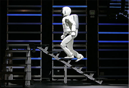
[NEWS] ASIMO Climb Stair


人類未來就靠我(2007/01/11)美國拉斯維加斯正舉辦的2007年「消費性電子展」(CES),10日會場上Honda公司展示新型小型的電池驅動機器人「ASIMO」,它也是全球唯一具備人類行走能力的類人型機器人,除了行走外,甚至可以爬階梯及坡道。Honda預計將此機器人融入未來人類日常生活中。(美聯社)